This project builds a solar powered dehumidifier solution for a boat stored in Florida. The dehumidifier can be run without any land based power through an inverter running off the house battery bank. The solution will manage the battery discharge and solar charging to ensure the house batteries are not abused.
Key components
12 volt deep cycle battery bank
120 volt inverter tied to house bank
Relay and a switchable inverter, where the on/off switch is run across the relay.
Arduino, small breadboard, a few resistors, jumper wires, leds and 9v power supply
High level design
The project will use an 120v inverter
that runs off the house 12volt battery bank, and an arduino to
measure battery voltage using a resistor ladder to step the
voltage down for the arduino, and control a relay that will turn
on the inverter. In my use case, I extended the on off
switch of the inverter to lead it to a relay controlled by the
Aurdino. When the relay closes, the inverter is switched on. If
this is not practical, you can have the relay control the
dehumidifier power cord, but in that case, the inverter is
always on and consuming power, which is less efficient.
The voltage trigger parameters can be changed in the code, but I have set the relay to fire when the battery voltage hit 13.4 which means we are being charged by the solar panels, hence the sun is shining and the batteries are fairly well charged. Once the relay is fired, the code will keep it on for a preset amount of time, in this case, I have set it to 3.5 hours. This way the batteries will not get run down too far, and the relay will not fire again for 9 hours (again, configurable) so I ensure we only run once a day. Checking the logs on the solar controllers can verify how your batteries and solar charging are handling the load through the day and adjust things as desired. As a way to ensure the batteries get fully charged, every five days, the code will enter a loop for two days where the relay will not fire no matter what the voltage is. This way, hopefully once a week, the batteries are 100% charged.
In my deployment, our battery bank is
600amp hours, and the dehumidifier draws 40 amps from the
batteries when running through the inverter, so without sun, we
would not run the batteries down too hard if the batteries are
at 100% when we start. There will be some contribution from the
sun as we do not fire the relay unless the batteries are at
13.4v showing they are being charged. The 950 watts of solar
panels contribute 50 amps in full sun, so overall, we should be
able to run the dehumidifier 3 hours for every 3 hours of
sunshine we see. In practice, the batteries tend to be fully
charged midway through days where the dehumidifier runs, and the
boat stays very dry and mold free.
Given the closed state of the boat, with little airflow, and the quart an hour dehumidifier rating, the running of the dehumidifier a couple of hours each day should result in two gallons or so of moisture being taken out of the boat each week. This should have a very strong impact on the humidity levels and hence mold growth inside the boat over the storage season (the summer months in our case).
Although not needed in the design, I
also wanted to be able to track the voltage seen by the Aurdino
for debugging sake, so I put together 8 LEDs in a row on my
breadboard and will light the LEDs to show the binary display of
the voltage as calculated by the Aurdino.
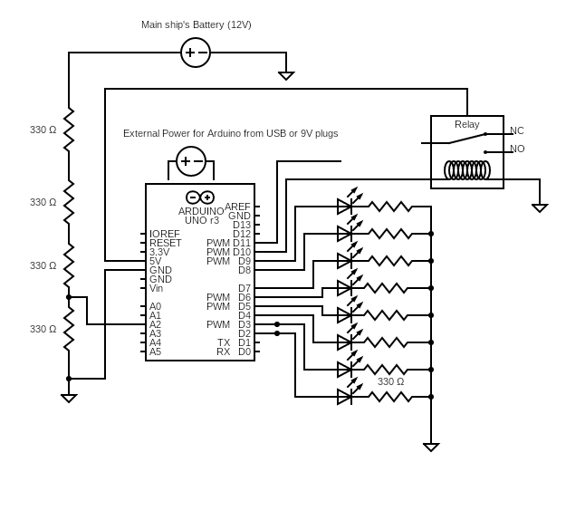
Here is a wiring diagram. The relay
can be used to turn the inverter on to power the load, or
switch the load on by closing the Hot wire of a live AC circuit.
The 8 LED’s provide a Binary count of the voltage as calculated
by the Aurdino. Since I drew this diagram, I have modified
the code to use the internal 3.3v pin as the reference voltage,
as the 5V internal reference voltage would vary depending on the
usb voltage powering the unit and made the voltage calculation
less accurate. Please put a jumper from the AREF pin to the 3.3V
pin to use the accurate 3.3v as the internal reference voltage
if using the code I supply.